How can we help?
-
Getting Started
- Articles coming soon
-
FAQs
-
-
- Are you ISPM-15 Certified?
- Can we select the delivery date and time once it has been shipped?
- Do you ship internationally?
- How are duties / taxes determined?
- How fast can I get one?
- How much is shipping?
- Is it classified as a medical device?
- Shipping & Delivery
- What are the shipping Crate Dimensions?
- What if my shipment takes longer than expected?
- What if something happens during shipping?
- What is your commodity code for international shipping?
- What is your HSN code for shipping abroad?
- Where is the dome shipped from? What should I expect once the dome is shipped and delivered?
- Can I buy a used dome?
- Can I pilot / rent a Somadome to trial it for my concept to determine if we want to move forward? Do you have used domes available for trials?
- Can we have multiple domes shipped directly to us?
- Do you also offer used domes for sale? If so, what are the terms?
- Do you do volume discounts?
- Do you have any options available for startups?/ Do you have any affordable options available?
- Do you offer any discounts?
- Do you offer full and partial financing?
- How does Pods 4 Peace work and how can I donate my dome for a write-off?
- How much does the Somadome cost?
- What happens after my purchase?
- What happens if I don’t want my dome after a period of time?
- What is your return policy?
- Where are you manufactured?
-
-
-
- (Who) When + How often should I dome?
- Do you have to charge the crystals embedded in the seat, under the moon or in water? Where can I find more information on your special tiles and crystals?
- How do I know it works?
- How does the Somadome work?
- How many people does it sit?
- I am claustrophobic. Will the dome work with the lid open?
- Is Somadome FDA approved?
- Is the dome safe for use during pregnancy and are there any other health medical contraindications?
- Is there any airflow inside the dome?
- Is this considered a Biohacking or Wellness device? What is the difference?
- What does Somadome mean?
- What healing modalities does Somadome use?
- What if I fall asleep inside the dome?
- What is it doing?
- What is the Somadome?
- What will it do for me?
- Who Founded Somadome and what is the idea behind it?
- Why dome?
- Show Remaining Articles3 Collapse Articles
-
- Can I contribute my content / how do you select your content?
- Can the dome lights be controlled while meditating?
- How many tracks or programs are in the basic configuration?
- If I buy my dome before your app comes out, how will I get new content? What will you charge me?
- Is the audio for the guided meditation tracks available in another language?
- Is the content in the Somadome only 20 minutes? Why?
- What is your content library / how is it growing?
- Which track should I choose?
- Will I get bored with just 20 sessions available if I am using this regularly?
- Will the SomaHome have longer content?
-
- Are there any customization options available for my dome?
- Are there specific network connection requirements?
- Can I replace the audio with my own audio?
- Can I use my earpods? Do the headphones connect via a regular audio cable or Bluetooth?
- Can you program codes for use, so someone couldn’t operate it without one? Is there a lock screen? Do any of your other tablets do this?
- Does Somadome connect to wifi?
- How can we change the light on our Somadome? Is there a setting?
- Why are you guys still using headphones with an audio cable? Don't you know that's outdated? Where's the bluetooth? Can I use my own BT headphones?
-
- Can I download the mobile app to the onboard touchscreen?
- Can I update the app operating locally on my onboard touchscreen?
- Do you have a VR / 3D tour of the Somadome experience?
- How much is the premium app going to cost?
- How will the app work with the Somadome?
- If I have a dome before you launch your app, can it still talk to the app?
- Is any of my data collected or transmitted?
- What is the IP status for Somadome?
- What is your technology roadmap and how will the product evolve?
- When is your app launching?
- Who writes your code?
- Will the design of the dome change?
-
-
- Can I change the power requirements? Do you have a plug for my market?
- Does Somadome have an energy efficiency rating?
- Does Somadome have UL or other international certifications/approvals for its electronics?
- Does the dome have any special power requirements?
- Does the Somadome generate any heat? Are there any specific HVAC requirements?
- Is there a CE certified power supply?
- What happens if there is a power outage? Can the electronics be damaged?
- What is the power/energy draw of the Somadome?
- How are sessions operated/how does a guest choose their session?
- How is the dome operated for partners not selling sessions?
- How is the dome operated for scheduling, use, and payment? for market partners selling sessions?
- What about after the session? What do we do?
- What about operations overall? Will it need someone to staff it?
- What happens if something breaks?
- What kind of ongoing support/maintenance does it need?
-
-
- Are there any ongoing costs with owning a dome?
- Do you provide virtual support?
- How do I get updates when you add new content or update the App?
- How much and how hard is it to retrofit if needed?
- How will legacy domes be updated? Are you changing the electronics on domes as you've been growing?
- We are across the world from you, do you have field techs in our market?
- Where are your service centers?
- Will I be included in software updates and updates to the session library?
-
- Are the lights covered by the warranty? What is the standard cost to replace them?
- Do I need an in house maintenance technician for the dome?
- Does the dome come with backup tablets or headphones?
- How do you service domes out of warranty or support us if something goes wrong?
- What happens if the dome gets scratched? Is it covered by warranty?
- What is the expected lifespan of the dome? And how long do these machines last?
- What is the oldest machine you have and do you have references for people that have these in their home?
- What is the warranty?
-
-
- Are there any negative side effects associated with listening to binaural beat meditations in the Somadome?
- Can I get the same kind of benefits from binaural beats as I could from meditation?
- How frequently do you have to meditate, or use binaural beats to have an effect?
- What are binaural beats?
- What does scientific research show about the effects of listening to binaural beat meditations on human health and well-being?
- Where can I learn about brain function changes over time?
- Why use binaural beats?
- Will it make me tired?
-
- How do I know if there is no EMF during a session?
- How do we know magnet therapy works?
- Is magnet therapy safe? Will it affect anyone with a pacemaker?
- Is there any radiation coming from the Somadome magnets or its technology?
- What are some examples of energy medicine?
- What does magnet therapy do?
- What is a low static magnet?
- What is energy medicine?
- Why is magnet therapy being used in the Somadome?
-
-
Tech Support
-
- Articles coming soon
-
- Articles coming soon
< All Topics
Print
Replacing the Somadome Control Board
PostedAugust 16, 2023
UpdatedAugust 16, 2023
ByInfo Admin
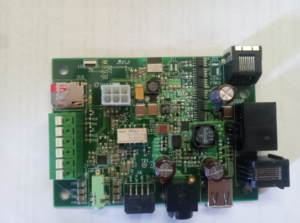
This document is designed to walk you through the replacement process of the Somadome Control Board. This is what your new Somadome control board will look like.
Before you start the replacement process please make sure that the Somadome has been powered off and unplugged from its power source. If the Somadome is still powered on and plugged in, you can risk shorting out the new control board.
- You will need to remove the lower rear panel. You will find the how to video here. It the lower rear panel removal will be found at the 1:38-1:56 minute mark.
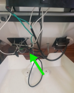
- Once you have the lower rear panel removed you will have access to the control board. The control board is being shown by the green arrow. I find that it is a good idea to take a clear picture of the control board while it is all hooked up. This way you will have a reference on how to reconnect the new one, once it is installed.
- Now you will remove the connected wire. Sometimes these can feel stuck, so please gently and slowly remove the wires. Once you have disconnected all the wires, it will be time to remove the old control board and replace it with the new one that has been sent to you!
- The control board is being held on to the Somadome by four screws. You will use a phillips head screw driver to remove these four screws. You will see where the screws are located with the red arrows, in the picture below.
- Once you have replaced the control board with the new one, use the picture you took of it to reconnect all of the wires. Once they are connected to you, before you close up the rear panel. Please plug the Somadome back into the outlet and power the dome on. Once it has completed the start up, please select a session to ensure the control board is properly connected. A properly functioning control board will change the light and play audio according to the session that has been run. Once you have had a successful session, you can now close up the lower rear panel! Below is a picture of the control board properly connected to the wires.
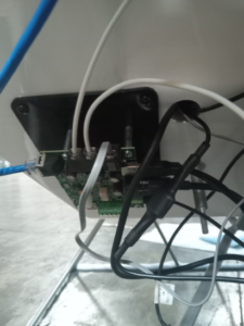
Table of Contents